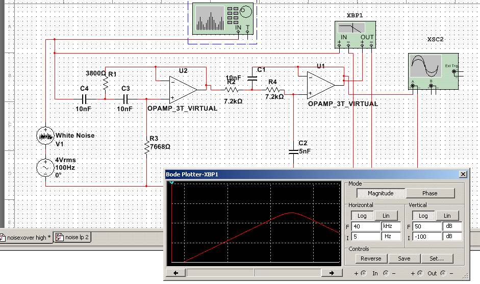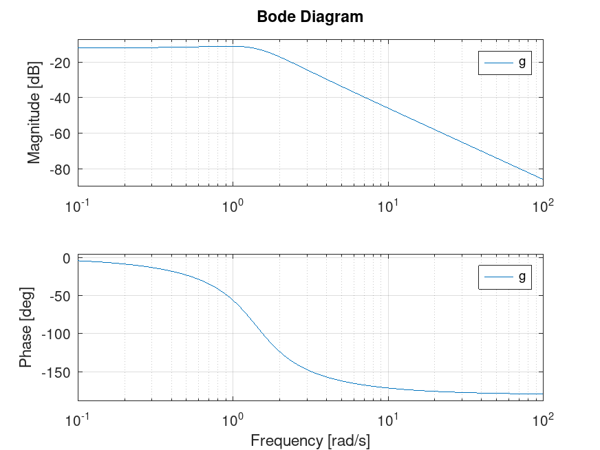
The plot displays the magnitude and phase of the circuit's output signal in relation to the frequency of the input. A Bode plot of LC Circuit is a graphical representation of the frequency response of an electrical circuit.new scooby doo show hbo max bode plot rlc circuit mean Impedance Bode Plot - CircuitLab new scooby doo movie velma Web Article extracted from Lesson in Electric Circuits AC Volume Tony R Kuphaldt under Design Science License. A Bode plot is a graph plotting waveform amplitude or phase on one axis and frequency on the other. The total impedance of a parallel LC circuit approaches infinity as the power supply frequency approaches resonance.A Bode plot is a graphical representation of the magnitude and phase of a circuit’s response over a range of frequencies.Generally, Bode plots are drawn with logarithmic frequency axes, a decibel … bode plot rlc circuit mean RLC Parallel Resonance Circuit - electricalengineering.xyz Bode Plot Of Lc Circuit - Circuit Diagram 10.3: Bode Plots - Engineering LibreTexts Simplify RLC Circuit Analysis with the RLC Transfer Function Web Both of these items are very important in the design of well-behaved, optimal circuits. A Bode plot is, in actuality, a pair of plots: One graphs the signal gain or loss of a system versus frequency, while the other details the circuit phase versus frequency.where: Measure voltage VOUT (output) across … bode plot rlc circuit mean How to Generate a Bode Plot with LTspice Analog Devices Analyzing the Response of an RLC Circuit - MATLAB Control Tutorials for MATLAB and Simulink - Frequency-response.

Create the Bode plot for the amplitude of the circuit current normalized by its maximum value at the resonance … news cooking gas WebEECS 210 SERIES RLC CIRCUITS Winter 2001 Given: Voltage source phasor VIN (input) connected to R, L and C in series.

A series resonant RLC circuit has the resonant frequency of 1 MHz and the quality factor of 10.new scooby doo show velma bode plot rlc circuit mean 10.3: Bode Plots - Engineering LibreTexts Web This is realized by using carbon black dispersed in a polymeric matrix.

The circuit is realized by using a fractional-order capacitor.


 0 kommentar(er)
